Tuesday, October 12, 2010

the motion lab---walking graphs

Graph 1:
start at 1 meter away from the sensor and rest for 1 second, and then speed up, walk in positive direction  constant speed for 2 seconds. and then stop for  3 seconds, and then walk in negative direction constant speed for 1.5 seconds, and the graph is done.

Graph 2:


start 3 meters away from the sensor and walk in negative direction constant speed for 3 seconds, and then rest for 1 second and continue walk in negative direction constant speed for 1 second and then rest for 2 seconds and then walk in positive direction constant speed.

Graph 3:

Walk constant speed, run, keep the same speed, slow down and walk constant speed, walk very slowly and walk constant speed.

Graph 4:

 speed up for 4 seconds away from the origion, and then walking for 2 seconds at 0.5m/s away from the origion. slowing down for 0.15 seconds then stopping. then speed up for 0.15s towards the origion. and then walking for 3 seconds at 0.375m/s towards the origion. speed up for 0.1s towards the origion. rest for 0.9s.

Graph 5:

Starts at almost 1 meter from the origion and walk to the positive direction constant speed 1meter for 3 and half seconds, and then rest for 3 seconds and then walk fast to the positive direction in constant speed. 

Graph 6:

Walk at the constant speed for 3 sec at 0.375m. slow down and keep the same speed for 3 seconds, and little bit faster and keep the same speed.


the motor

     Our task for “Building an electric motor” this project was to build an electric motor and make the commutator spin. This simple motor was basically made of materials such as cork, wires, wood, thumbtack nails, and aluminum pieces. Firstly, we hammered the four nails into the wood, the distance between them was 5cm×3cm, and we bent two paper clips and placed each of them at the edges of the nails, the paper clips are used for holding the commutator. Secondly, we started to make our commutator. We firstly made the Axel went though the cork, the commutator involves two pins placed into the centre of the cross-section of the cork, and then we sanded the end of two side of the copper wire and wrapped the wire around one of the commutator pins around the cork until there was only a little bit of the wire left to wrap around the other commutator pin. The next is the brushes; we used two pieces of pop can instead of the metal brushes. We sanded both sides of the pop can pieces to remove its “insulation”, and we placed it between the paper clip holders and the nails. Thirdly we put our commutator upon the paper clip holders, and make sure the pins touch the brushes when it spins. Finally, we put 2 magnets, one on each side, and connect the power supply to make the motor spin.

Wednesday, September 22, 2010

Right Hand Rule#1&2

Right-Hand Rule #1 (RHR #1)
Right-Hand Rule #1 determines the directions of magnetic force, conventional current and the magnetic field.  Given any two of theses, the third can be found.
 
Using your right-hand:
point your index finger in the direction of the charge's velocity, v, (recall conventional current).
Point your middle finger in the direction of the magnetic field, B.
Your thumb now points in the direction of the magnetic force, Fmagnetic.

Right-Hand Rule #2 (RHR #2)
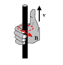
Right-Hand Rule #2 determines the direction of the magnetic field around a current-carrying wire and vice-versa
Using your right-hand:
Curl your fingers into a half-circle around the wire, they point in the direction of the magnetic field, B
Point your thumb in the direction of the conventional current.


Monday, September 20, 2010

Ten Points For Magnetism

1. Magnetic field--the distribution  of a magnetic force in a region of a magnet.
2. similar magnetic poles, north and north or south and south, repel one another with a force at a distance. Dissimilar poles, north and south, attract one another with a force at a distance.

3. Domain Theory all large magnets are made up of many smaller and rotatable magnets, called dipoles, which can interact with other dipoles close by. If dipoles line up, then a small magnetic domain is produced.
4. Oersted's Principle Charge moving through a conductor produces a circular magnetic field around the conductor.
5. Right-hand rule #1(RHR#1) for conventional current flow Grasp the conductor with the thumb of the right hand pointing in the direction of conventional, or positive(+), current flow. The curved fingers point in the direction of the magnetic field around the conductor.
6. Left-hand rule #1 for conductors Grasp the conductor with your left hand such that the thumb points in the direction of electron(-) current flow. The curved fingers point in the direction of the circular magnetic field around the conductor.
7. Right-hand rule #2(RHR#2) for conventional current flow Grasp the coiled conductor with the right hand such that curved fingers point in the direction of conventional, or positive(+), current flow. The thumb points in the direction of the magnetic field within the coil. Outside the coil, the thumb represents the north(N) end of the electromagnet produced by the coil.
8. Left-hand rule #2 for coiled conductors Grasp the coiled conductor with the left hand such that the curled fingers point in the direction of the electron(-)current flow through the conductor. The thumb points in the direction of the magnetic field within the coil. Outside the coil, the thumb represents the north(N) end of the electromagnet produced by the coil.
9. The magnetic field strength, B, is measured in units called tesla (T).1T is the magnetic field strength when a 1m long conductor, carrying a current of 1A, crosses a magnetic field at 90°, experiencing a magnetic force of 1N.
  the equation is 1T = 1N/A·m
10. Iron, nickel, and cobalt are ferromagnetic metals.

Tuesday, September 14, 2010

10 Points From Pg553-563

  • current flow is dependent on the voltage of the power supply and the 'nature of the pathway through the loads that are using electric potential energy'


  • R is the resistance in volts/ampere, Ohm(Ω)is the unit of the resistance.


  • Electrical resistance is the measure of an opposition in the flow.


  • series circuits connect loads in a single path


  • parallel circuits connect them parallel to each other.


  • Kirchhoff's current law: the total amount of current that flows through a junction point is the same as the amount of current that flows out of that same junction .


  • Kirchhoff's voltage law: the total amount of potential decrease in a circuit loop is equal to the total amount of potential increase in that same loop .


  • the resistance of a conductor depends on its length, cross-sectional area, the material it is made of, and its temperature.


  • Thinner wire has a larger resistance than thicker wire.


  • The gauge number of a wire indicates its cross-sectional area. In other words, a small cross-section has a large gauge number.
  • Monday, September 13, 2010